Hydrophone
This revision is from 2018/08/01 16:44.
Professional or marine biology hydrophones are expensive and not quite easy to find. But it is possible to build one using piezo disk for a reasonable price and with decent quality.
The basics of the presented hydrophone is to use two piezo disk together to reduce noise and increase output level. The circuit provide a balanced output and allow the use of great length of cable. It is entended to be used with a XLR phantom powerd input.
Piezo disk are high impedance devices, and although the hydrophone can be used as they are, a dedicated preamplifier can significantly inprove sound quality and improve low frequency responce.
The hydrophones presentent here are inspired by the work of sound artist David Dunn who extensively worked with piezos.
The preamplifier electronic circuit is originaly from Alex Rice, now offline, and provided by sound artist and Locus Sonus Soundmap collaborator Zach Poff.
An aquatic live stream from Zack Poff is present on the Soundmap, or here right from the server.
More information about the specificity of piezo microphones can be found here.
Our first take at hydrophone was a two disk balanced circuit encased between two thick piece of laser cuted plexiglass.
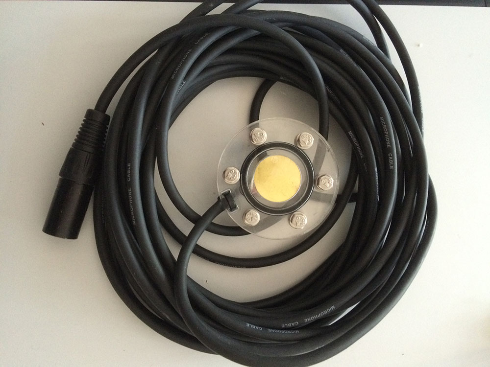
But it was not that good, due to the thickness of the plexyglass.
The second take was better. It use a David Dunn's tow chained piezo circuit, glued at the bottom of a thuna can. The used can was already coated witch provide electric isolation from the piezo disk to the can. The can is used as a shield an solder to the ground wire of the XLR plug.
You will need a thuna can (or of other food, the fish do not matter, but the size do), and two piezo disk.
Using epoxy, glue the piezo at the bottom of the can. The brass part of the piezo must be cuted to fit in. Be carefull that the brass part of each piezo do not touch one another. It is a good idea to prepare the solder joint on the piezo before glueing them.
Solder the microphone wire as shown. On the other side of the cable, on the XLR plug, solder the red wire to hot(2), the blue one to cold(3. Using a sharp tool scrap the coating of the can to expose the metal (if yours is coated) and solder the shield wire to the can. On the XLR plug side, the shield goes to the ground(1).
Then fill it up with epoxy resin, or silicon.
This hydrophone is suitable for clear water, but will rust quickly in salt water. It will need some sort of coating to resist sea water.
If you are going to the sea, I strongly suggest a gold coated XLR plug. Experience have shown that corrosion is just everywhere.
The preamplifier (Alex Rice original design).
This preamplifier use FET transistor, and power itself from the +48v of the phatom power supply. It output a balanced signal, suitable for great length of cable.
You will need:
Capacitors:
220pf x3
Resistors
3 M ohm x4
150 ohm x1
1.2 K ohm x1
Transistors
j201 x3 (equivalent of the PF5102, drop in compatible)
Stereo microphone cable.
A male XLR plug.
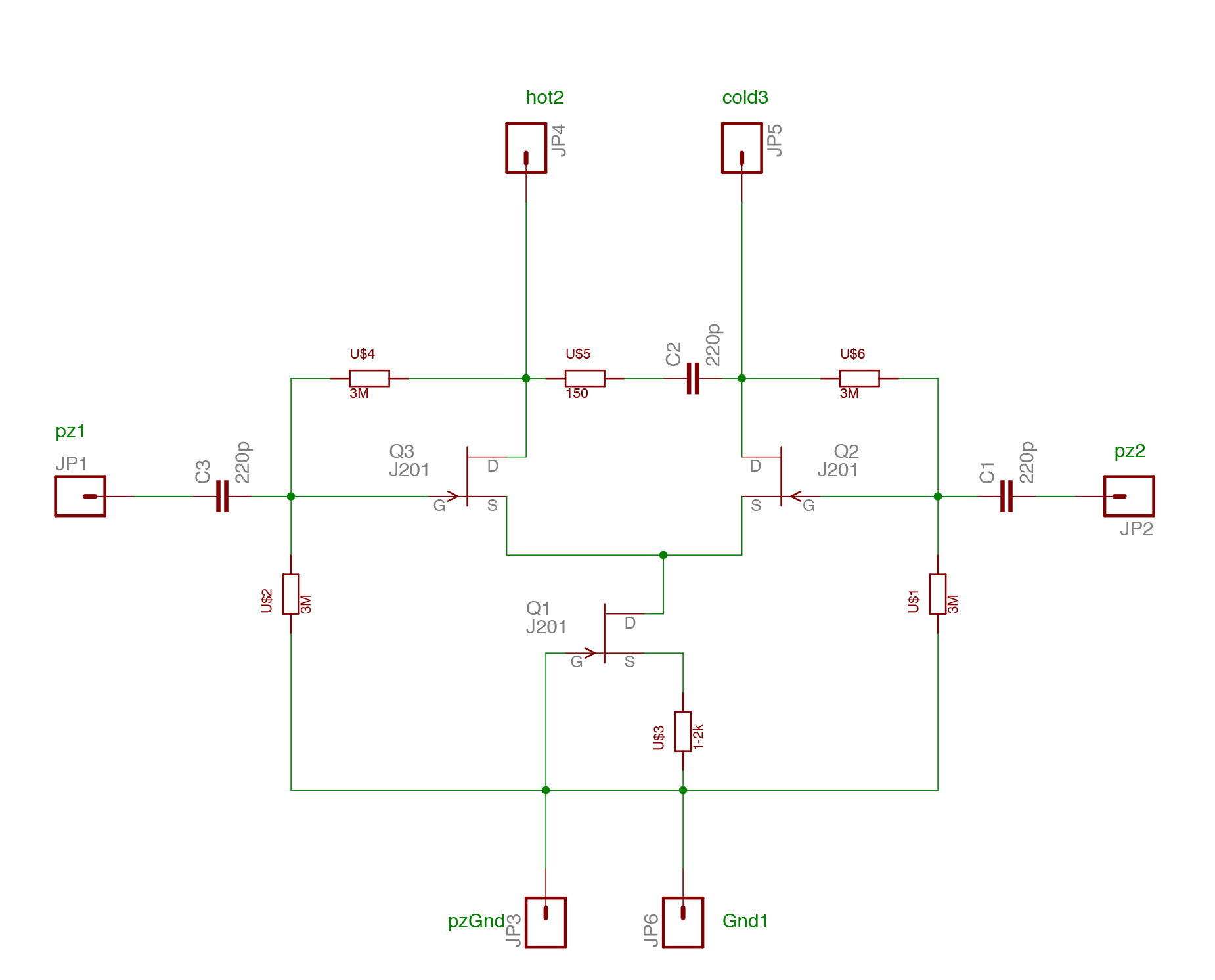
The schematic.
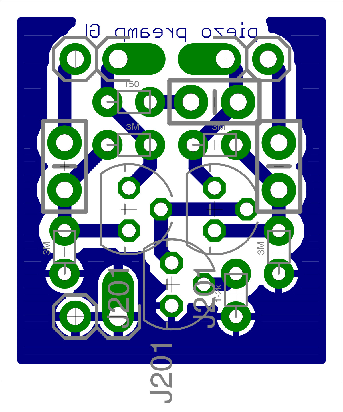
Implantation of the parts with the provided PCB design.
If you want to print your own PCB, here are the eagle files.
But it can be done on test board as well. The crystal part of the firs piezo goes to pz1, the brass part of the second piezo goes to pz2. Then hot goes to 2 on the XLR plug, cold to 3, and ground to 1.
Experimental hydrophones
-Thuna can #2
This version of the thuna can hydrophone came from the idea that the closer the piezo to the medium transmiting the sound, the better.
The circuitry is the same as in the thuna can one, but the piezo disk are brought in contact with the water. The can still act as a shield for interferences. A piece of 3d printed material is used to hold the piezo in the right place and exposed.
The preamplifier is embeded in the can, making it a must be phantom powered device. It is then filled with epoxy resin, and coated with resin to resit sea water.
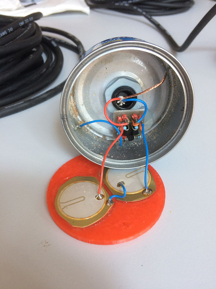
The piezo and electronic assembly. The piezo disk has been cut to fit the narrow space. Hot glue gun was used to secure the circuit board.Epoxy glue was used to attach the piezo disk to the 3D printed support.
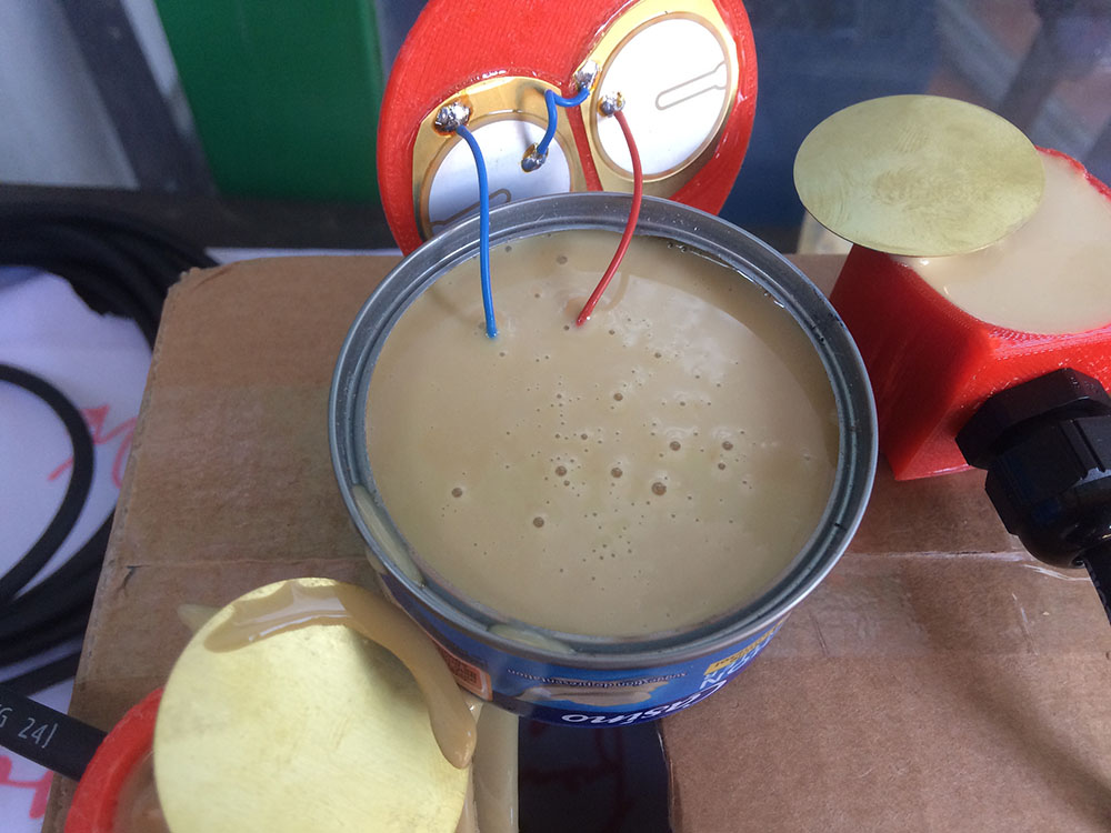
Then it is filled with epoxy resin. The resin fully water proof the circuit, and provide weight to make the all thing not buoyant. You want your hydrophone to sink, not float. Once the resin poured, the lid is put in place and the can is flipped so the resin goes everywhere. Leaks may occur.
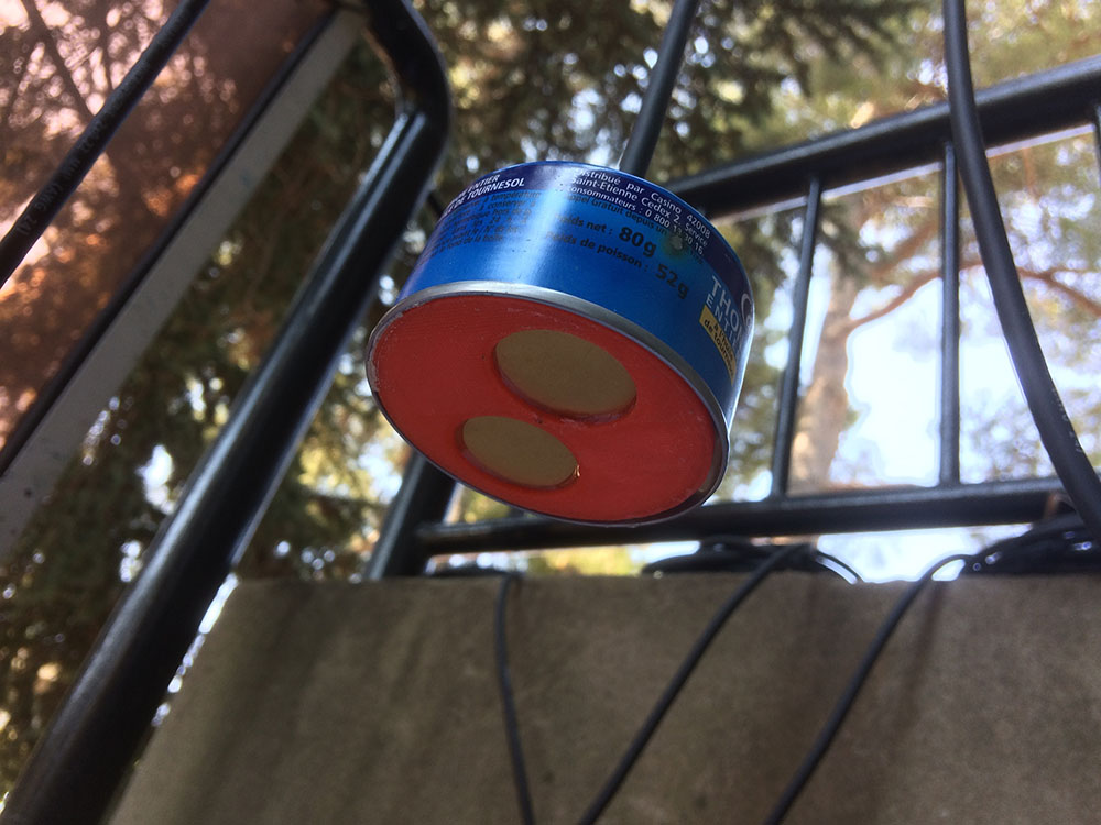
Once the resin cured, the hydrophone is ready for coating. Notice how the piezo disk are in contact with the outside.
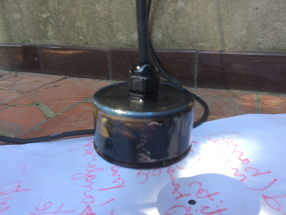
And here it is fully coated and ready to use.
-Fully shielded hydrophone
This one is very similar to the one above, except that the box is fully closed and shielded. The preampliflier is embeded as well. The piezo disk are glued to the lid of the box, witch is flat in the difference of the thuna can bottom. The flatness of the lid provide a better contact. A piece of plastic was glued between the piezos and the lid to prevent contact. An extra piece of wire must be used to link the lid to the case for complete shielding. The used box, a pipe tobacco box, was slighty coated and needed to be scraped before soldering on it.
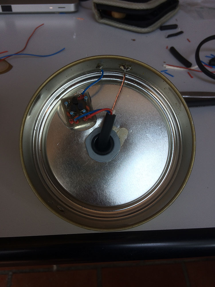
The preamplifier circuit is hot glued to the case, shield solder joint are made.
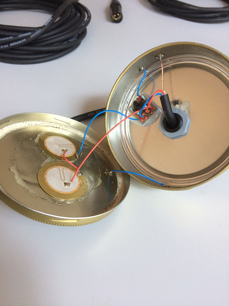
Piezo disk are glued with a protective plastic sheet, and wired to the preamplifier.
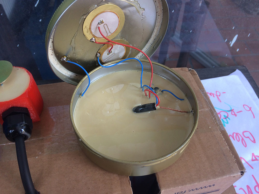
It is then filled with epoxy resin to fuly water proff it. The lid is put back on and the all thing tilt over. No leak this time.
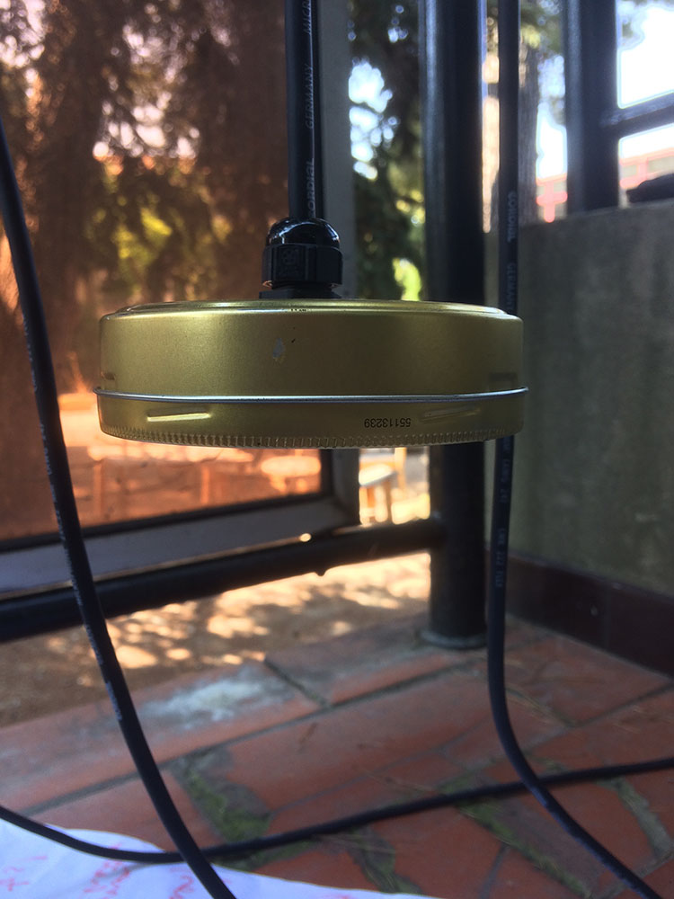
The all asembly is ready for external coating.
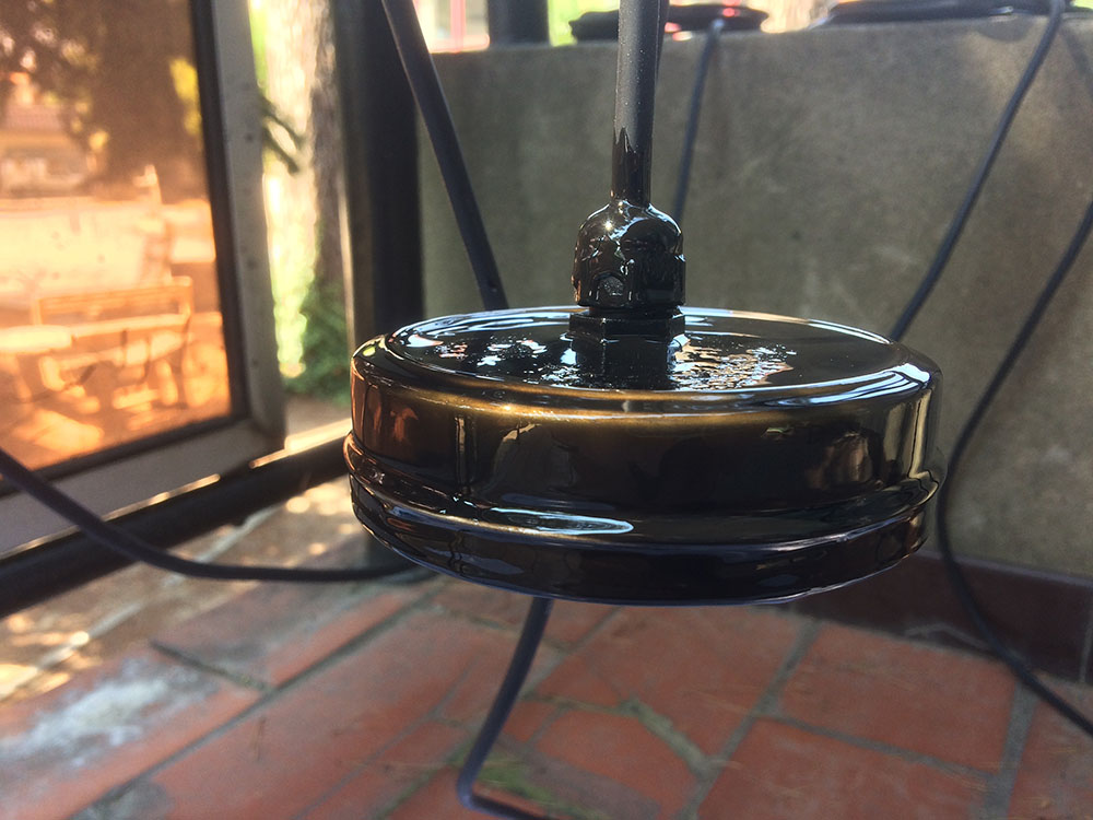
The fully shielded hydrophone with external coat, ready for the sea.
So far, this design is the more sensible. It tend to be directional and more suitable when used hanging from hsi cable than sunk at the bottom.
Last changed 2018/08/03 23:09